TWR - Al-Najaf Tower
Chapter 1. Position Overview
Al-Najaf Tower (TWR) controls aircraft on the runway, aircraft holding at runway holding points, and aircraft operating within the Class D Al-Najaf Control Zone. The TWR Controller is responsible for all aircraft within the Al-Najaf CTR and shall ensure traffic information is provided between IFR and VFR flights.
At Al-Najaf, ORNI_TWR is responsible for the entirety of the CTR and is required to provide top-down service if Al-Najaf SMC is offline.
The TWR Controller is responsible for selecting the active runways for arrivals and departures at Al-Najaf and holds full authority over the runway.
| Position | Callsign | Frequency | Logon Callsign |
|---|---|---|---|
| Al-Najaf TWR | Al-Najaf Tower | 119.100 | ORNI_TWR |
| Al-Najaf SMC | Al-Najaf Ground | 121.700 | ORNI_GND |
| Al-Najaf ATIS | 123.900 | ORNI_ATIS |
Chapter 2. Airspace
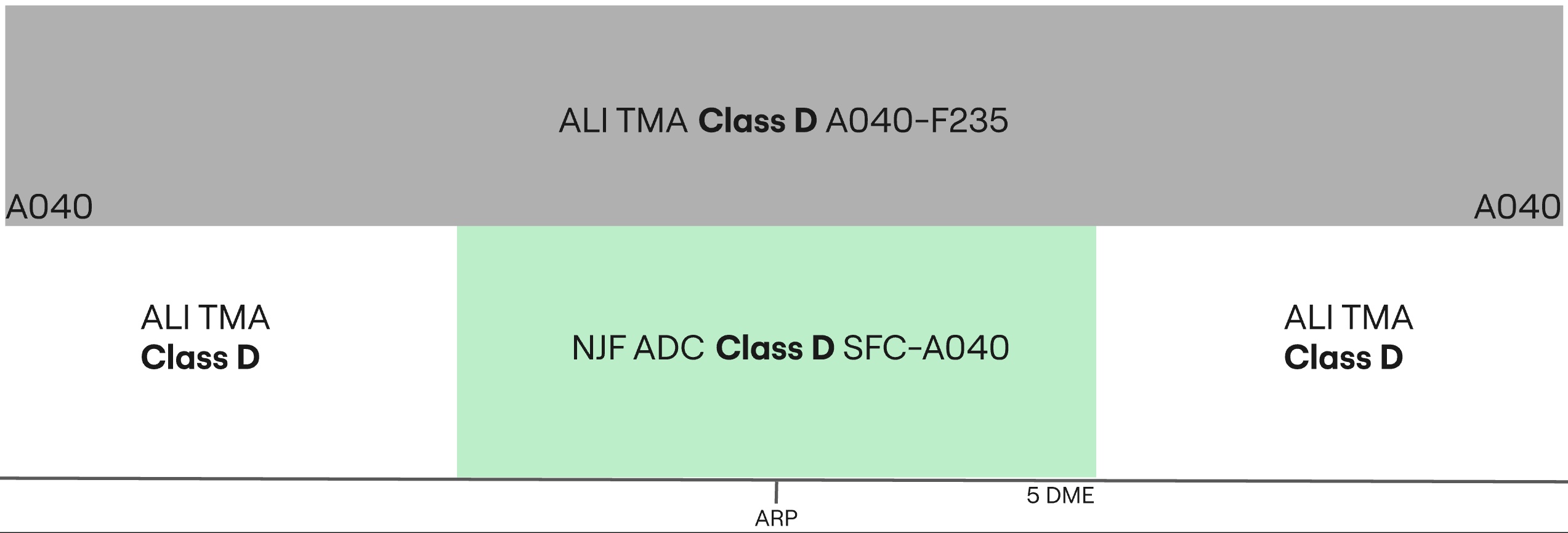
The Al-Najaf Control Zone (CTR) is Class D Airspace from the surface up to 4000ft. The TWR Controller is responsible for IFR arrivals and departures as well as VFR aircraft operating within, entering, or exiting the CTR.
Chapter 3. GEN | Standard Operating Procedures
3.1 Runway Selection
Winds must always be considered for runway modes. Crosswind must be less than 20 knots and tailwind must be less than 5 knots. The preferred order of runway modes at Al-Najaf is listed below.
| Priority - Mode | Arrivals | Departures | Remarks |
|---|---|---|---|
| 1 - MODE A | 28 | 10 | Opposite direction operations |
| 2 - MODE B | 10 | 28 | Opposite direction operations |
| 3 - MODE C | 28 | 28 | |
| 4 - MODE D | 10 | 10 |
This preferential runway configuration applies opposite runway direction operations. This may not always be possible due to weather conditions, specifically when the tailwind component is greater than 5 knots, or due to high traffic volumes where opposite direction operations are unsuitable.
3.1.1 Runway Change
If the TWR Controller deems it necessary to change the active runway due to wind, traffic flow, or operational requirement, this shall be coordinated with Al-Najaf SMC and the relevant Baghdad TMA controller. Runway changes must not be implemented suddenly, as they affect departure releases, SID assignment, arrival sequencing, and issued clearances.
3.2 Line Up Procedures
The TWR Controller must issue clear and precise instructions when issuing aircraft with an instruction to line up on the active runway. The instruction should include the runway designator, the holding point at which the aircraft is to enter the runway, and any relevant traffic information.
Example:
TWR Controller: "IAW23, via D, line up and wait runway 10."
3.2.1 Conditional Line Up Clearance
The TWR Controller may issue a conditional line-up clearance in order to maximise runway efficiency. The condition must be clear and precise, and the word behind should be used at the start and end of the instruction.
Example:
TWR Controller: "IAW23, behind the landing Iraqi Airways Boeing 737, via D, line up and wait runway 10, behind."
3.3 Take Off Procedures
3.3.1 Standard Instrument Departures (SIDs)
All aircraft shall normally be assigned a Standard Instrument Departure (SID) by Al-Najaf SMC. Controllers shall assign the proper SID exit waypoint based on the first enroute waypoint in the aircraft's flight plan, and the proper procedure identifier based on the selected runway for departure.
All SIDs with an identifier of 1A and 1C are valid for Runway 10. SIDs with an identifier of 1B are valid for Runway 28.
| SID | Runway 10 | Runway 28 |
|---|---|---|
| SIGBI | 1A | 1B |
| ILMAP | 1A | 1B |
| LAGLO | 1A | 1B |
| NOLDO | 1A, 1C | 1B |
| SEPTU | 1A | 1B |
Departures should primarily adhere to the published SID routes, avoiding radar vectors whenever feasible. If radar vectors are assigned, a specific reason must be provided.
3.3.2 Omni-Directional Departures
Aircraft may be assigned an omni-directional departure if they are unable to fly a SID, or for departures to the southwest filing via RUKAM or ALI DCT RUKAM.
If a departing aircraft is receiving an omni-directional departure, they must receive an assigned heading with their line-up or take-off clearance. Al-Najaf TWR shall coordinate with the overlying TMA controller on a heading to follow after departure before issuing a take-off clearance.
Unless coordinated otherwise, TWR shall assign the following headings:
| Runway | Heading |
|---|---|
| 10 | H160 |
| 28 | H330 |
The runway headings H100 and H280 shall be avoided when possible.
Special consideration must be given to prohibited area P102 west of the airport when Runway 28 is in use for departures. This prohibited area protects the Holy Shrine, and flights shall, when possible and when not following SIDs, avoid the area by flying north of the Holy Shrine. VFR flights shall also be guided to avoid this area when possible.
3.3.3 Take Off Clearances
Aircraft should only be given take-off clearance once the runway is clear of obstructions and separation from any previously departed or arriving aircraft has been achieved.
Example:
Pilot: "IAW23 ready for departure."
TWR Controller: "IAW23, after departure climb to altitude 4000ft, fly heading 160 degrees, surface winds variable at 3 knots, runway 10 cleared for take-off."
3.3.4 Handing Off
Departing aircraft shall be transferred to the relevant Baghdad TMA controller once safely airborne and released from Tower jurisdiction.
Example:
TWR Controller: "IAW23, contact Baghdad Approach 122.400."
3.3.5 Stopping a Departure
In the event a departure must be stopped after take-off clearance has been issued, the instruction must be issued immediately and clearly.
Example:
TWR Controller: "IAW23, stop immediately, I say again, stop immediately, runway incursion."
For an aircraft that has not yet begun the take-off roll, cancel take-off clearance and instruct the aircraft to hold position.
Example:
TWR Controller: "IAW23, hold position, cancel take-off, I say again, cancel take-off due runway incursion."
3.4 Arrival Procedures
The TWR Controller is responsible for issuing landing clearance and ensuring that arriving aircraft have a clear and unobstructed runway before landing.
3.4.1 Landing Clearance
Example:
Pilot: "Al-Najaf Tower, IAW123, final runway 28."
TWR Controller: "IAW123, Al-Najaf Tower, winds 260 degrees at 8 knots, runway 28 cleared to land."
3.4.2 Late Landing Clearance
If landing clearance may be delayed due to preceding traffic vacating slowly or a departure ahead, the aircraft may be advised to expect late landing clearance.
Example:
TWR Controller: "IAW123, expect late landing clearance, one to vacate ahead."
3.4.3 Vacating Traffic
All departing aircraft shall be assigned the most appropriate taxiway onto Taxiway C. Al-Najaf TWR and SMC must exercise extreme caution on Taxiway C, as conflicts can easily occur between arriving and departing traffic.
Example:
TWR Controller: "IAW123, vacate via C, contact Al-Najaf Ground 121.700."
3.4.4 Go Around Procedures
The TWR Controller shall issue go-around instructions if the runway is obstructed, separation is lost, or landing clearance cannot be safely issued.
Example:
TWR Controller: "IAW123, go around, I say again, go around, acknowledge."
Once the aircraft has acknowledged the go-around, Baghdad TMA shall be notified immediately. After a go-around, the next departure from that runway requires next coordination.
3.5 VFR Procedures
All VFR clearances are assigned by Al-Najaf TWR. VFR procedures inside the Al-Najaf CTR must be conducted at or below A040.
VFR departures should be given departure instructions, including turn directions, routing or leg to exit the circuit when appropriate, and altitude. VFR aircraft shall be assigned an SSR code.
Aircraft may request a touch and go, stop and go, low approach, or full stop. Once the TWR Controller is aware of the aircraft's intentions within the CTR, they may be sequenced to the runway with due consideration given to runway occupancy time and IFR traffic.
3.5.1 Traffic Remaining in VFR Circuit
VFR circuits are permitted on Runways 10 and 28. Aircraft wishing to remain in the circuit at Al-Najaf shall be issued not above A040 and the following circuit directions:
| Runway | Circuit Direction |
|---|---|
| 10 | Right-Hand |
| 28 | Left-Hand |
VFR circuits shall not be permitted during periods of increased IFR departure or arrival activity.
3.5.1.1 VFR Circuits Phraseology
Pilot: "Al-Najaf Tower, ABC holding short D runway 10, fully ready."
TWR Controller: "ABC, Al-Najaf Tower, cleared to operate in the circuit area not above altitude 4000ft, right hand circuits report downwind, surface winds 320 degrees 5 knots, cleared for take-off runway 10."
Pilot: "Cleared to operate in the circuit area not above altitude 4000ft, will report right downwind, cleared for take-off runway 10, ABC."
3.5.2 Zone Exit Clearances
Once VFR aircraft are ready for departure, they shall be cleared for take-off in sequence. As they begin their crosswind turn, they shall be instructed to report leaving the Al-Najaf CTR.
Aircraft requesting to exit the Al-Najaf CTR shall be assigned a clearance limit followed by a valid VFR cruising altitude.
Example:
Pilot: "Al-Najaf Tower, YYC is requesting to exit the Al-Najaf CTR via direct Baghdad, altitude 5500ft."
TWR Controller: "YYC, Al-Najaf Tower, cleared to leave the Al-Najaf CTR direct Baghdad, maintain altitude 5500ft, squawk 7403, QNH 998 hectopascals."
Pilot: "Cleared to leave the Al-Najaf CTR direct Baghdad, maintain altitude 5500ft, QNH 998, squawk 7403, YYC."
Once airborne:
TWR Controller: "FYI, report leaving the Al-Najaf CTR, maintain at or below altitude 4000ft."
3.5.3 Inbound VFR Traffic
Inbound VFR aircraft shall be sent to Al-Najaf TWR with enough time for two-way radio communications to be established before aircraft receive clearance to enter the Al-Najaf CTR.
On initial contact, Al-Najaf TWR shall pass instructions for joining the circuit and any other relevant traffic information. During times of heavy IFR arrival activity, VFR arrivals may be denied entry into the CTR and instructed to hold outside the CTR awaiting further instructions.
Example:
Pilot: "Al-Najaf Tower, YYC is requesting to enter the Al-Najaf CTR from the south for circuits."
TWR Controller: "YYC, Al-Najaf Tower, information A, cleared to enter the Al-Najaf CTR, maintain at or below altitude 4000ft, report left downwind runway 28 with intentions, squawk 7403."
Pilot: "Information A, cleared to enter the Al-Najaf CTR, at or below altitude 4000ft, will report left downwind runway 28 with intentions, squawk 7403, YYC."
TWR Controller: "YYC, correct, QNH 998 hectopascals."
Chapter 4. Coordination
4.1 Departure Procedures
Due to the airspace structure at Al-Najaf, all departures shall be coordinated and receive a release for departure with the relevant Baghdad TMA controller.
Next coordination is required to the following stations in the following scenarios:
| Coordination Station | Departing Procedure |
|---|---|
| ORBI_APP | All SIDs except ILMAP departures, and omni-directional departures expected to enter Baghdad TMA, mainly departures to the north |
| ORNI_APP/ORMM_APP | ILMAP departures and all other omni-directional departures |
ORNI_APP/ORMM_APP must be notified of aircraft that are being released on an omni-directional departure to ORBI_APP.
Next coordination is additionally required for:
- Visual departures; and
- The next departure from that runway after a go-around.
The standard assignable level from Al-Najaf TWR to Baghdad TMA is:
| Aircraft | Level |
|---|---|
| IFR | A080 |
| VFR | A050 |
Next coordination is mandatory for all aircraft departing Al-Najaf.
Example:
TWR Controller: "IAW123 for release, SIGBI1A departure, any problems?"
TMA Controller: "IAW123 released, SIGBI1A departure, all is good."
4.2 Standard Assignable Departure Headings
If a departing aircraft is receiving an omni-directional departure, they must receive an assigned heading with their line-up or take-off clearance.
| Runway | Heading |
|---|---|
| 10 | H160 |
| 28 | H330 |
If strong winds are present at altitude, TWR and TMA should discuss slight changes to these headings to compensate for large crosswind components.